Designing the micromouse motor control is a key task which will go a long way to determining the performance of the mouse in the maze. Before that can be done, you will need to know the physical characteristis of the motors and the drive system. All that can be calculated as part of the design process but it is easier to measure it if you already have the mouse built…
The mouse can be treated as a second order position control system with a fairly simple transfer function.
![]()
Where Tm is the overall time constant and Km is the DC gain. These turn out to be tricky to calculate but remarkably easy to just measure. The mouse has two control systems, one for forward motion and one for rotational motion. they can be treated as completely separate for the purposes of modelling. Here, I will deal only with measuring the rotation parameters because it is easy to do without finding a long stretch of maze. The mouse only has to spin on the spot.
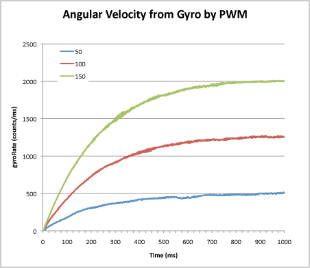
To collect the required data, the mouse is given a fixed PWM drive to the motors. Positive to the left motor, negative to the right motor. Any control funtions are turned off and the mouse is allowed to accelerate up to a constant angular velocity. The angular velocity is measured every millisecond and the result recorded on a chart. Do this for several values of PWM. They are likely to be small values like 5-20%. You should see a set of results like these:

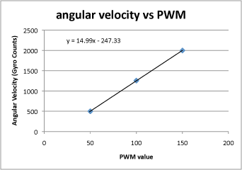
Notice that the shape of each curve is the same. It is an exponential of the form K*(1-exp(-t/Tm)). Eventually, the angular velocity will reach a steady value. Record that value by averaging over some suitable period – say 1 second or so – along with the PWM value that caused it and plot those values on another chart. Fit a straight line to the chart:

The slope of this chart is your DC gain, Km. In this example, you can see that the line does not go through the origin. This is because of losses in the drive system. It takes a certain minimum value of PWM drive before the mouse can even move. Thus, you cannot determine the gain just by measuring the steady state angular velocity at just one drive level. For this mouse, I can see that the angular velocity, as measured by the gyro is approximately 15 times the pwm drive. The units are arbitrary but here will be ADC readings (after subtracting the bias) for the gyro and the PWM is simply the value placed in the PWM register on the processor. Here it wil be in the range +/- 1024. Since the readings are taken every millisecond, the gain will actually be 15,000 counts/sec/pwm.
Next, I want the time constant, Tm. I can get a good estimate from the graphs by finding the time where each graph passes through an angular velocity that is 63% of the steady state value. This is because 1-exp(-1) = 0.632. Alternatively, you could use the spreadsheet to calculate an exponential and play with the gain and time constant until you get a good fit. For this mouse, the value of Tm is 0.215 seconds.
So now I have my transfer function for rotational movement.
![]()
Exactly the same process can be carried out for the forward motion controller. My thanks to Harjit Singh for originally pointing out this method of determining the system characteristics.
Pingback: 數位相位超前控制器心得 | 嵌入式控制系統實驗室
Pingback: 設計一個電腦鼠的數位相位超前控制器 | 嵌入式控制系統實驗室
And what about the control system for the forward motion. How will we get the equation for that.