Although easy to calculate and easy to perform, an in-place turn with
your micromouse is a big time waster. That type of turn generally requires
that the mouse comes to a complete halt, turns around and then sets off
again. While this is probably the sensible thing to do in a dead end,
most turns will be a lot quicker (and draw admiring sighs from the audience)
if you can perform a smooth, coordinated turn with the mouse not seeming
to pause. This type of turn may be called a smooth, integrated, coordinated
or slalom turn. Whatever you call it, you should certainly try and do
one.
If you have a tricycle mouse, the soloution to these turns can be a bit
more simple as the primary mechanism for generating the turn is the steering
wheel. Indeed, if you also put a differential on the driving wheels, the
steering wheel will do the work. Two-wheel, wheelchair mice, must perform
the turn by careful coordination of the speeds of the two driving wheels.
 |
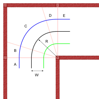
Have a look at this picture showing the track of a mouse performing a simple 90 degree, right turn in the maze. The coloured lines show the track of the wheels, blue for the outer wheel, green for the inner wheel. The black curve is the path taken by the centre of mass of the The radius of the turn is shown as R and will be 90mm assuming
|
The distance of the wheels from the mouse centre (half the track width)
is shown as W. For the examples below, I shall assume a track width of
80mm so that W has the value 40mm.
The thin red lines are the cell entry and exit points and the turn has
been divided into five segments
Segments A and E:
Since both wheels cross the entry and exit points at the same time, they
will need to be going at the same speed when they do so. This speed is
the entry velocity (Ve). It could be anything that suits but
I will assume it is the same as the average cornering speed. That is,
the speed of the centre of mass of the micromouse as it follows the black
path. In practice, you are likely to have come thundering down a straight
and will want to decelerate the mouse in a straight line to some suitable
cornering speed.
Segment C:
For at least part of the turn, the mouse will be turning at a constant
rate and the centre of mass will follow a segment of an arc with constant
radius R. Although I have shown R to be half a cell width, it could be
larger or smaller. The smaller R is, the greater the forces acting on
the mouse. A large value for R give a more gentle turn but you run the
risk of clipping the inside corner or over-running the outside. To work
with a larger R, you may decide to have your mouse move towards the outside
as it aproached the bend and come as close as you dare to the inside corner
on the way through. this is how you would do the turn if you were in a
racing car.
Segments B and D:
Clearly, during segment A, the wheels are turning at the same speed, equally,
during segment C, they are turning at a constant speed that is different
for each wheel. To get from segment A to segment C, the outer wheel must
accelerate while the inner wheel decelerates.
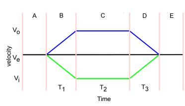
We can draw a graph showing the wheel speeds as the mouse goes through
the turn.
 |
As before, the green line show the velocity profile for the inner wheel, the blue line that for the outer wheel.
|
As a useful simplification, I have used a constant acceleration for the
wheels and applied the same value for each wheel. Also, the entry and
exit segments are show as at some constant speed, equal to the average
cornering velocity.
Calculating the values
First you will need to decide upon a safe average cornering speed for
your mouse. This will depend upon a num,ber of factors. For example, the
widthm height, mass, motor power, tyre material, recklessness, desperation
and so-on. Speed runs will use higher speeds and accelerations, exploration
will want to be pretty safe. Let us assume we want to be able to corner
at a fairly modest (and easy to work with) 100mm/s.
The actual path taken by the wheels will not be perfect sections of a
circle except during segment C. However, you will see later that the difference
is small so I shall ignore it for now.
The average path length for this turn will be a quarter of the circumference
of a circle with radius R:
P = 2*pi*R/4 = 3.14*90/2 = 141.3mm
At 100mm/sec, we would complete the curve part of the turn in 1.4 seconds.
The outer wheel has to cover a distance of
Po=2*pi*(R+W)/4 = 3.14*(90+40)/2 = 204.1mm.
Since we have to cover that distance in 1.4 seconds, the velocity (Vo)
will be 144.4mm/sec
For the inner wheel, we only have to travel a distance of
Pi=2*pi*(R-W)/4 = 3.14*(90-40)/2 = 78.5mm.
This we can do at a velocity (Vi) of only 55.6mm/sec
The transition phases (segments B and D) mean that we must accelerate
or decelerate the wheels as appropriate. Suppose we have set our maximum
acceleration to be 0.1g which is nearly 1000mm/s/s (and is not terribly
high).
The outer wheel must accelerate from 100mm/s to 144.4mm/s. This will
take only about 0.044 seconds, during which time the wheel will have travelled
a mere 5.4mm. At the end of the turn, segment D takes the same time and
distance. So when I assumed the path was essentially circular, it turns
out to be circular for all but 11mm. Close enough.
It is not quite true to say that the inner and outer wheels accelerate
and decelerate at the same rates or that they take the same amounts of
time to do so. However, it is a good enough approximation for now and
the differences are small compared to the other errors present in a real
mouse.
Implementation
Well, how does this work out for a real mouse. In general, you will need
path-planning outines that can control the motors during each phase of
the motion, ensuring that the wheels achieve target positions and velocities
at the appropriate times. You task is made easier by the relative symmetry
of the problem. Not only does the inner wheel slow down by about the same
amount as the outer wheel speeds up, the turn is in two symmetrical halves.
Once you are half way, you can reverse the procedure on the way out. Similarly,
left turns are the same as right turns with the wheels reversed. Since
we always cross the cell boundary with the wheels going at the same speed,
combining turns is quite easy.
The simplest example is for a stepper driven mouse. Here, we do not have
infinitely variable speeds and accelerations in most cases without a lot
of real-time calculations. Instead, the steppers are likely to be driven
from timing tables. For a given acceleration, there will be a fixed table
of values determinnig the time between steps and hence the velocity. If
you were to do the calculations properly, you would need to rearrange
things to work in the distance domain as steppers move in fixed size steps.
This is not worth the effort if you dont want to do it.
Instead, I will give you an example using the speeds calculated above
and the values from the tables on one of my mice. This mouse can accelerate
at 2.5m/s/s and is happy to turn the wheels at speeds of up to 500mm/s.
Here is the first part of the acceleration table calculations done in
Excel:
|
Step number |
Elapsed Time |
Distance (mm) |
Velocity |
stepper freq |
|
1 |
0.018941 |
0.46 |
24.3 |
53 |
Cornering at 100 mm/s average speed means that my motors will be doing
about 224 steps per second with timing values coming from entry 5 in the
table. The closest I can get to the calculated speeds will be 149.1 mm/s
(entry 10) for the outer wheel and 58 mm/sec (entry 2) for the inner wheel.
Once I am at the appropriate point to begin the turn, travelling at 103
mm/s, I arrange for the inner wheel to decelerate for 3 steps and the
outer wheel to accelerate for 5 steps. These take approximately the same
amount of time and the transition is over in less than 3 mm of travel.
Now I run at those speeds for a suitable number of steps – about 440 for
the outer wheel and 170 for the inner – before allowing them to work their
way back to their previous speeds and we will be travelling straight again.
Suppose testing showed I had miscalculated slightly? If it is a small
problem, the turn can be tightened or loosened by having the outside wheel
accelerate my one more or one less step respectively. With a stepper mouse
and fixed acceleration tables, all actual travelling speeds are an approximation.
With a stepper mouse and taking a simple approach, I do not have to construct
special acceleration tables for turns, I just need to precalculate the
speeds and distances for each phase and work through the segments until
I am done.
Printermouse uses this approach and seems to work just fine.