A typical wheelchair driven mouse has a pair of drive wheels and skids, rollers or castors of some kind in front of and behind the wheels. For most of the time, three points of contact are used and the weight of the mouse is shared between the wheels and one or the other skid. The more weight you have on the skid, the less there is available to provide accelerating and decelerating forces through the wheels. Furthermore, as you accelerate or decelerate, there will be some weight transfer to the skid, reducing the down force through the wheels and reducing their grip. If you have a combination of low coefficient of friction and large weight transfers, there is the possibility that your mouse will skid under heavy acceleration of braking.
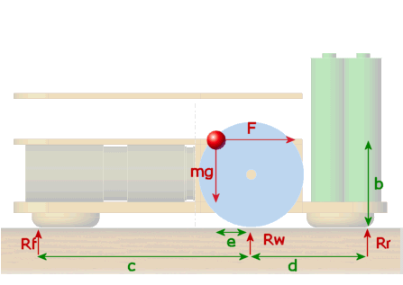
For the least weight transfer, the Center of mass of your mouse should be a low as possible. To allow symmetrical acceleration and deceleration, the Center of mass should be over the drive wheels. Weight transfer will be reduces if the skids ar as far away from the drive wheels as possible. Below is a representation of a wheelchair mouse. This one is Florence.

Distances are shown in green, forces are shown in red. The Center of mass is the red blob. the mass of the mouse is m and the acceleration due to gravity is g. The acceleration of the mouse is a.
The force F represents the accelerating of decelerating force. It is pointing backwards in this drawing to represent a restraining force while the mouse is acceleration. By restraining the mouse with the force F, we can use simple moments and equations from statics to see what is going on. Florence would normally travel to the left as seen in this drawing. The battery pack has been placed to keep the Center of mass near the wheels. The distances to the skid has been shown to the actual point of contact rather than the Center
| Acceleration |
| We can take moments about the point of contact of the wheels to find out something about the force on the rear skid. We get
mge + RRd – Fb – RFc= 0 RR = RFc +(Fb – mge)/d Since F = ma RR = RFc + m(ab – ge)/d You can immediately see that, if d is large, the force on the skid will be small. There is, of course, a limit on the size of d if we want to be able to get round corners. Beside that, the rules have a maximum mouse length of 250mm. There will be a value for a that makes RR zero. Since d is not zero or infinite, and m is not zero, RR will be zero when RF is zero and ab = ge a = ge/b For Florence, b = 20mm and e = 8mm and she has a mass of 250g. Thus, at an acceleration of 0.4g (3.92m/s/s), all the mouse weight will be over the drive wheels. Beyond that and the force on the rear skid will increase and the force on the front skid will be zero. Suppose Florence can manage 0.5g (4.9m/s/s – pretty optimistic!). The value of RR will be RR = 0.25 * (4.9 * 20 – 9.8 *8)/35 RR = 0.14N Since the total weight of the mouse is 2.45N, we have transferred a tiny 6% of the weight away from the wheels. So Florence can accelerate fairly hard and not lose too much traction. You get nothing for nothing so what is the cost? First, by having the CG in front of the wheels, there is a loss of force through the wheels under small accelerations. This will not be too significant for Florence as the front skid is 65mm away and so, when standing still, 89% of the weight is over the wheels – plenty to get going. Second, deceleration performance will be reduced.
|
| Deceleration |
| A similar analysis to that above will allow us to calculate the weight transfer during braking.Assume again that we want to achieve 0.5g deceleration. Now, RR will be zero and we can write an expression for RF. Remember that F will have changed sign.
mge + mab – RFc= 0 RF = m(ge + ab)/c Once again, making c as large as possible will reduce the weight transfer. In Florence, c has the value 65mm and with a deceleration of 0.5g we would have RF = 0.25 * 9.8 * (8 + 0.5 * 20)/65 RF = 0.68N So nearly 28% of the mouse weight is transferred to the front skid, leaving a down force through the wheels of 1.77N. OK – so what? will there be enough friction to decelerate the mouse at this rate with that much down force? The force needed to decelerate the mouse is F = ma = 0.25*0.5*9.8 = 1.225N The coefficient of friction required to manage this is µ = 1.22/1.77 = 0.69 That turns out to be a bit tricky. While typical tyres may have a static friction coefficient of 0.8 or more, it may not be safe to assume you can get better than 0.5-0.6 in an actual maze. If we can only manage a coefficient of friction of 0.5, we will have only 1.77 * 0.5 = 0.885N of usable braking force giving a maximum deceleration of 3.54m/s/s (0.36g) To be honest, I would be happy getting anywhere near that.
|
| Summary |
Firstly, all this is only of any interest if you think you are going to be able to (or want to) build a truly competitive mouse. Making the thing go at all is plenty of achievement so don’t assume you have to live on the edge.Leaving aside all the tedious sums, there are some handy conclusions that would, in all honesty, have been pretty clear if you just thought about it a bit.
|