 Soon after listening to the presentation by Martyn Pittuck at Minos12 about Shapeways printed parts, I designed and ordered the motor mounts for my micromouse, Decimus 4. The design part was a bit harder than I expected because of a poor decision taken previously about the PCB outline but ordering the parts was easy. The hardest part was waiting for them to arrive. Today, they did.
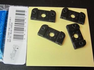
I ordered four mounts at £5 each. Not really cheap but well worth saving several hours careful machining. I chose the Black Detail material as it is said to be very accurate and the last thing I wanted was to have trouble with the gear meshing.
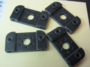
On unpacking, I was a little disappointed with the quality of one part compared to the others but it looked like it would not be a problem since all the key dimensions and locations seemed just fine.
Close examination showed that the surface finish looked good but seemed a little waxy. I should look to see if this is just partial curing at the margins of each layer or some other aspect of manufacture. Either way, it was not much of a problem for the outer surfaces.
The holes for the location and mounting of the motor and axles were very accurate with the motor being a nice snug fit and all six mounting screw holes accurately placed and sized.
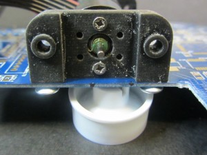
At the bottom of the mount are the holes used to fix the mounts to the board. It is here that I made a mistake. The design had these holes at 2.5mm with a view to tapping them M3 for the mounting screws. Trouble is, the material is not as strong as you might like for tapping such a fine thread. On the first two mounts, I tapped the holes properly, full depth and screwed them to the board. The screw threads stripped out straight away. From where you sit, that might have been how it was always going to end but I had not thought it through. Not to worry, I had two more. For these, I just ran in a few threads. Enough to get the screw started. After that, I let the screw form its own threads by displacement. These seem solid enough but I am not sure whether to trust them. Here you see a mount temporarily screwed to the board with whatever screws came to hand. The motor sits beautifully in place held firmly by its M1.6 screws. This is a Faulhaber 1717 motor. It all looks scruffier than it is because I didn’t bother to clean up before taking the picture.
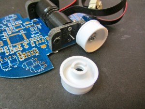
I have reservations about how well the board mounting screws will hold after a few knocks. If I am to carry on using these, I may have to cross-drill the mounting holes and insert some plastic or aluminium dowels with proper threads in them. That is certainly what I will have to do with the other mounts that I stripped the holes out of. Note that the wheels shown in these photos are not the ones I will be using. I need a smaller diameter. Perhaps I will get them made by Shapeways.
With both mounts on the board, and the motors attached, it is also apparent that these mounts may not be as strong as I might hope. There is a certain amount of flexing and it is the motor, firmly tightened against the rear face that is responsible for much of the longitudinal rigidity. Now I understand why I see some mice of this configuration with solid axles joining the two sides. I think I will have to do that here.
By the way, if you have a lathe and want to make light weight rods and axles, old knitting needles – the metal kind – make good stock.
This was an interesting experiment. I am happy with the accuracy and, considering the work involved in making them myself, the price is reasonable. Especially since a quick visit to the web site will bring me as many more as I want. Clearly, it pays to understand the material better and there are some things I might do differently now I have seen the finished article and got a bit of a feel for its properties.
It is quite likely that I will have some wheels made – if only to let me produce unmachineable patterns.
At some point, I must test for IR reflectance and transmissivity because this might make good sensor holders to assist with alignment.
Shapeways can be found at http://www.shapeways.com
Are the encoder in the picture the 16 lines per rev. version (the black cable) ?
Can you give me some info on the mini-z wheel, because i also want to use them but i don’t understand if they have already one or two bearing and also where do you buy them?
Thank you.
Those are the 16 line encoder version. I shall not be using those particular motors on this mouse. They were just handy for testing the fit. MiniZ wheels can best be found through a Google or Ebay search. There are a lot of suppliers and a huge range of different wheel styles. They don’t come with bearings but the people who sell the wheels often sell bearing sets that match.
For this mouse I will need custom wheels anyway because of the mistake I made in the board dimensions.
Pingback: Micromouse wheels made by rapid prototyping | Micromouseonline
Hey Peter,
how did you securely mount the small gear onto the motor shaft without damaging the motor?
Greeting from Germany
– Hannes
It was a scary moment – I was probably lucky. When your pinions seem to take too much force to fit them, you do not have many options. If you have access to a uitable drill you can try opening out the pinion. If you overdo that, you can tighten the fit by putting one or more strands of sewing thread through the pinion before pushing them onot the shaft.
Alternatively, at the risk of damaging the motor shaft, you could run the motors and use very fine sandpaper to reduce the shafts a little.
Sometimes, the problem is that the motor shaft end raises a burr on the inside of the pinion as it is pushed in. Try chanfering the hole or the shaft end or both.