A good side-looking
wall sensor will return an analogue value representing distance to the wall.
The simple presence or absence of a wall is inadequate for steering. The
greater the level of accuracy, the better. In principle a sideways looking,
reflective sensor will give better results than a top-down sensor. However,
variations in wall reflectivity, from cell to cell and maze to maze can
make this difficult to use. You could try some kind of auto calibration
while the mouse is running although it is likely that you will need manual
calibration at the start of a run.
One of David Otten’s mice was observed to have suffered from this kind
of reflectivity problem. If I remember correctly, in one competition maze,
the posts had different properties to the walls. Thus, the mouse was not
able to reliably detect wall edges and had serious navigational problems. The sensors i use have to be calibrated for the actual maze it runs in. Some time I may get round to some kind of autocalibrate.
The simplest sensor is going to measure the intensity of light reflected
from the wall and use it as a measure of distance. Even if you have a
consistent reflective surface there will be problems.
The amount of reflected light will change non-linearly with distance.
This is the result of the inverse square law. The intensity is proportional
to one divided by the square of the distance. A non-linear amplifier could
be used to compensate for that. If you don’t then accuracy will become
a function of distance – it will be better for a close wall than a far
wall.
The cosine law determines the amount of reflected light in terms of the
angle of incidence. Now the intensity is proportional to the cosine of
the angle. This effect is not as marked as that for distance. For example
the intensity may only change by 10% or so with angles up to plus or minus
25 degrees. The problem comes with smooth, shiny surfaces. Essentially,
the more shiny the surface, the worse the problem. Don’t paint your maze
walls with gloss paint. Think of a mirror. When the light is perpendicular
to the mirror, all of it is reflected back at the source. Change the angle
just a little and all the light will be reflected away from the source.
You may overcome some of the limitations of the inverse square law by
using more directional light sources and sensors, and devices are available
with lenses for this purpose. Focussing the light may make the cosine
law problems worse without some extra care regarding alignment.
Combinations of cosine and inverse square law effects may make it difficult
to adequately determine offset and heading errors in your mouse. Many
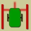
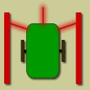
mice that employ reflective sensors point them a little forwards.
 |
 |
|
|
perpendicular sensors |
angled sensors
|
The effect of this is that a mouse with a heading error only will still
see a big difference in sensor readings from left to right whereas perpendicular
sensors will show the same reading as if the walls had receded on both
sides. Another advantage is that you move the sensing point further forward
which will help with the dynamics of the steering control.
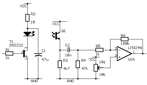
The following circuit is pretty much lifted from the circuitry of GENESIS
2.

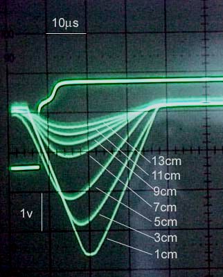
Tests with a static set-up on a breadboard give encouraging results with
surprisingly little variation from angle of incidence. (The cosine rule
is moderately forgiving after all). The composite oscilloscope trace illustrates
its use. A 7 microsecond burst on the emitter would be followed 10us later
by capturing the analogue value at the output of the amplifier

I tested it on my oscilloscope (without opamp, up to R4). Looks like the 10n(C2) and 4.7k (R4) works as a noise (room-light) cancellation filter. I am an undergraduate Electrical Engineering student. What is the concept behind the filter? And what type of filter is it? Looks like a high-pass filter. But this is not an AC circuit. I want to know the theory behind it. Could you pls help?
With a good choice for the IR detector and a reasonably fast ADC on the processor, you may well not need anything in the receiver circuit after R3. However, for this circuit…
C2 is a DC blocking capacitor. It is there simply to remove the standing voltage across R3 due to the ambient illumination.
R4 ensures there is a reasonably short decay time after changes in the level across C3
The rest is just a DC amplifier with a fairly high gain.
Thsese days, I would have only the IR detector and the emitter resistor. Values for these are chosen so that I get a dynamic range of a couple of volts response when the emitter is pulsed over the distances I am interested in and so that the ambient illumination does not cause saturation. Then the value is read once with the emitter off and again with the emitter on. The difference between the two is the signal due only to the emitter.