Feeling our way with sensors

The sensors are a critical part of a micromouse. Primus uses six infra-red reflective sensors. Here is code to test that they are working.Now that we have a nice display to show what the sensor reading are, we can get that module tested. Since the hardware is very simple, there is not a lot to go wrong. Yet somehow I had a dead sensor when I first tested the Primus prototype. It was a simple dry joint that would have been detected by more careful inspection of the board. (more…)
Continue ReadingFeeling our way with sensors

Adding a timer and the graphical LCD

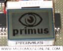
primus micromouse splash screenThis is a fairly big jump. With the LEDs and buttons tested, it is time to add the main graphical display, made from a Nokia cellphone display. Also, there is the main system timer event.

The simple user IO is working, and it is time to add a system timer. This will generate an interrupt every millisecond. In the final mouse a lot of work will be done in here – processing buttons, driving the LEDs, reading sensors and calculating drive signals for the motors.While that may seem a lot in a millisecond, the dsPIC used in primus can execute about 16,000 instructions in that tme and we should only need a small proportion of that time. (more…)

Continue ReadingAdding a timer and the graphical LCD

Revised schematics and pin functions

After a bit more thought, there is now a new set of pin assignments for the Primus micromouse, along with a corresponding schematic.The problem with Primus was that it is not possible to generate two independant pulse trains from the PWM generators. All the PWM channels have to share a common time base.The Output Compare peripherals on the dsPIC30F4011 can generate up to two independant pulse trains in hardware but one of the time bases must come from Timer 2 which is needed for counting steps sent to the motors. One of the fundamental design decisions on Primus is to drive the two steppers at high speeds without any interrupt service routine soaking up processor cycles.It seems that one motor will have to be driven from an OC channel and the other from a PWM channel. (more…)

Continue ReadingRevised schematics and pin functions

A bit of a change to Primus

It seems I made a bit of a mistake in how I thought the dsPIC could drive its PWM module. Consequently, there will have to be some changes.First, what can’t change is the need to use T1CK and T2CK as external inputs to count motor pulses. There are no other choices on the dsPIC30F4011 without using interrupts. Since I anticipate pulse rates of up to 100,000 Hz per wheel, life will be a lot easier not having to service that interrupt rate, even with a fast processor and a very efficient ISR. (more…)

Continue ReadingA bit of a change to Primus

Robosavvy bipeds at ROBOtic’07

The guys from Robosavvy forum have confirmed that they will yet again be demonstrating their bipedal wares at ROBOtic'07, and are intending to run several competitions.The bipeds were very well received at UK Micromouse 2007, and a promised demonstration of stair climbing could mean that they reach even greater heights…

Continue ReadingRobosavvy bipeds at ROBOtic’07

A little bit of test code

Once the main board is assembled, it can be tested without waiting for the sensor or motor driver boards to be ready. In time honoured fashion, we start with a little program to flash the LEDs.With any new microcontroller project, it is a good idea to start with some simple code that will allow you to test your ability to create a project in the chosen development environment, compile the program, transfer it to the microcontroller and run it. While you are at it, you get to test the simplest part of the system hardware. (more…)

Continue ReadingA little bit of test code