Selecting the best micromouse sensor design is a study in electronics, physics, geometry, maths and coding. Here I will look at some of the design considerations for the sensors in the next iteration of my micromouse.
Zeetah V and VI use triangulation sensors pioneered by David Otten. These sensors consist of a narrow beam emitter coupled with a Position Sensitive Detector (PSD) which has a lens in front of it. The idea is that the emitter illuminates a spot on the wall and then the lens images the spot on to the PSD. As the distance between the sensor and the wall changes, the location of the spot on the PSD moves. By determining the location of the spot on the PSD, you can tell how far the wall is from the sensor. What is super nice about this approach is that it is wall reflection intensity insensitive. The downside is that it requires precise location of the emitter, detector, lens and two trans-impedance amplifiers per PSD.
However, almost all other mice are very successfully using a much simpler scheme consisting of an emitter detector pair. So, for Zeetah VII (ZVII), we are going to move to the simpler sensor.
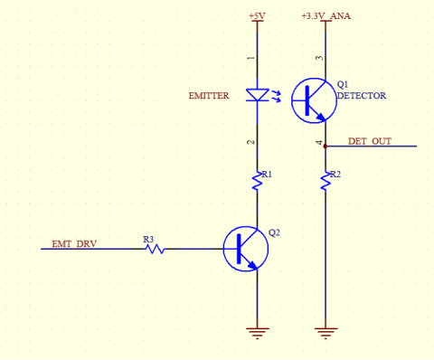
The basic circuit of the simple sensor is as follows:
There are many choices for the emitter, detector, emitter drive level, detector bias and whether you should have an AC cap between the detector and the ADC.
This write up will walk you through the design for ZVII.
The emitters that I looked at were: L2791, L2388-01, SFH4545, VSLY5850, SFH4550.
The criteria for the emitters was narrow angle and high irradiance.
The detectors that I looked at were: TEFT4300, TPS601A, LTR4206E, SFH313, SFH309, SDP8436, VEMT2023SLX01, OP805SL.
The criteria for the detectors was they must have an IR filter, wavelength compatibility with the emitters and ability to handle the high ambient light levels that are present at some contests. In the list, the TPS601A is the “golden” standard because many Japanese mice use this sensor and it works well. However, it has been discontinued.
After looking at the compatibility between the emitters and detectors, I narrowed the list down to the SFH4545 emitter and the TEFT4300 and LTR4206E detector. The SFH4545 is a very narrow angle (+/-5° half angle) and most importantly, the emitter pattern doesn’t have any stray side patterns.
The TEFT4300 and the LTR4206E have light current to irradiance curves that are similar to the TPS601A. Several contestants have published schematics for their mice and using these, I came up with the detector resistor (R2): TEFT4300: 1.8K; LTR4206E: 1.0K.
The sensor reading procedure is as follows:
- With the emitter off, read the detector
- Turn on the emitter
- Delay for the detector response time
- Read the detector
- Turn off the emitter
- Sensor reading = detector with emitter on – detector with emitter off
The next decision was the emitter current level. The emitter current was determined by setting up a wall that was 20mm (the closest I wanted the sensor to work well) away from the emitter and detector and adjusting the emitter current until I got a reading that was approx. 90% of full scale of the ADC range. The SFH4545 current ended up being 125mA.
Next, I adjusted the emitter on time. I did this by turning on the emitter and then reading the detector every 20uS. I looked at the detector data at 20uS, 40uS, 60uS and 80uS and noticed that the detector value changed from 20uS to 40uS but then was stable after 40uS. I also verified this by looking at the detector waveform on an oscilloscope.
To make sure I had the detector sampling time correct, I repeated the experiment ten times and looked at the standard deviation of the readings at each time sample and made sure the standard deviation didn’t change between 40uS, 60uS, and 80uS.
The detector sampling time I picked was 40uS.
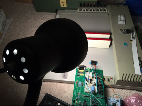
The next step was to gather data for the sensors as a function of the distance. A friend made me a black Delrin block that has a 3mm hole, a one 5mm hole and another 3mm hole all in a line. The detector to emitter center to center distance is about 7mm. The LTR4206E was mounted in the left hole; the SFH4545 in the center hole and the TEFT4300 in the right hole. The detectors and emitter were connected to resistors and drive electronics on a proto board. The proto board was connected to a STM32F411 mbed development board.
The block was mounted to the bed of an old plotter. The wall is mounted to the plotter arm using double sided tape – see picture. In the picture below, the walls move between the sensor block (bottom of the picture with “L” and “T”) and the top of the picture).
The test program on the PC commands the sensors to do a reading and then it commands the arm to move to a new position. By doing this over and over again, we gather Sensor VS Distance data.
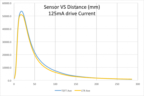
Here is sensor data for the emitter being driven at 125mA:
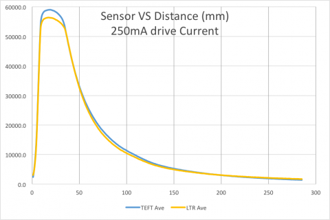
The X-axis is the distance between the block and the wall in mm. For the first few positions, because of the geometry, the detector is not able to see the light from the emitter. After approximately 18mm, the detector has a good view of the emitter.
The Y-axis is the sensor reading in ADC units. The processor I use has a 12bit ADC. For the graph above, I show the value for ten sensor readings for each position. In actual usage, the mouse will perform one reading per position.
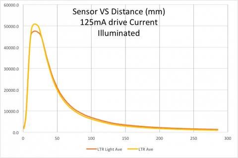
In the picture of the setup, on the left side, you can see a lamp. The lamp has a 60W light bulb. I did a run with the light turned on to see how the sensor responded to the higher light level. Below is the sensor data. What is nice about the sensor is that the general shape is not affected by the light. Also, the difference between the two curves is one to three mm. So, it should be possible to adjust for this at the contest. I am not sure if I will make the adjustment by changing the offset of the curve automatically or manually. This is an area I am way behind compared to other people since I have not had to deal with it before – all suggestions for what works and doesn’t work are greatly appreciated!
I wanted the ability to detect longer distances, so I did another run with the emitter current increased to 250mA. Here is detector data:
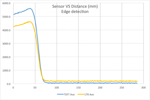
A significant difference between the TEFT4300 and the LTR4206E is that the TEFT4300 has a large half angle. So, I also wanted to compare the sensor readings when they saw a falling edge. What is interesting is that the sensors take 20mm to go from a wall to no-wall reading. In reality, one cannot wait this long to make the falling edge decision. So, it is desirable to pick a sensor where the slope for a falling edge is very steep. Based on this, the TEFT4300 has a slight edge over the LTR4206E. Here is the falling edge sensor data:
Since the emitter is narrow angle, the fact that the TEFT4300 has a large half angle doesn’t affect this measurement.
In conclusion, ZVII will use the SFH4545 emitter with either the LTR4206E or the TEFT4300 detector.
Very nice post! I’m building linefollowers myself and can really appreciate how much work you put in a topic like this,
excuse me, I´m building a minisumo robot but I don´t know how transform de adc sign to distance (mm), can you help me please?
Hi, Thanks for the informative article. I want to ask a silly question, I already have SFH4550 (peak wavelength 860 nm) and TEFT4300(940 nm) lying around me. From their datasheets it seems they are pretty much incompatible but still what are the chances of making them work together for obstacle detection ?
I tried for SFH4545 too but both of my local distributors Element14/Farnell and RS components (India) dont have it in stock.
Again sorry for the stupid question.
Thanks!
The wavelength of the emitter has to be within the receive wavelength of the detector. The TEFT4300 sensitivity compared to the peak is 5%. The matching is too poor to work well.
Thanks for the confirmation, I too had the same doubt. Maybe I will change the detector for a matching wavelength with SFH4550.