A robot like the micromouse needs to be able to make accurate, repeatable and stable turns. The rotation centre is the point about the robot will turn in place. For a two-wheeled robot, it should be halfway between the two contact patches. If it is not, the turns will leave the robot out of position. Here I will show you how to accurately find the centre of rotation.
Please note that I am only dealing with robots that can turn in place. This will not apply to most robots with steering wheels such as bicycles, tricycles and cars. It will apply to two-wheel balancing robots, tank- and skid-steer robots, and most designs of micromouse.
Rotation of robot in place
The first thing to realise is that, if your robot makes a turn-in-place of 360 degrees, it should end up exactly where it started. That will be the case regardless of where the centre of rotation is. If that is not clear, just take a piece of paper, put your finger anywhere on it to create a pivot point and turn the paper by 360 degrees. It will be exactly where it started.
If you try this with your robot and it does not end up in the starting position, you have a problem where the centre of rotation changes as the robot turns. That should not happen and you will have to carefully consider both the hardware and software to be sure that everything is as it should be.
In this article, I am assuming the 360 degree turn leaves the robot correctly positioned.
A simple robot
Consider a simple, two wheeled robot where steering is done by turning the drive wheels at different speeds. Something like this micromouse for example:
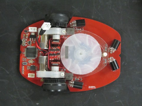
Let’s simplify this as diagram. The drive wheels are left out. Two lines represent the principal axes of the robot. One line runs longitudinally through the centre of the robot. At the front and back, marks on the robot show the end point of this line. in the photo above, you can see notches that serve the same purpose. Another line goes through the centres of the driving axles and so through the contact patches where the tyres meet the floor.
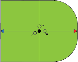
The solid black circle, where the two lines meet is where the centre of rotation should be. The other circles represent cases where the centre of rotation is not in the right place. For now, assume that the centre of rotation is also intended the centre of the robot. That need not be the case and I will deal with that later.
Basic test
The robot is placed on the ground with marks on the floor indicating the position of the red and blue arrows on the robot. Now, if the robot makes a 180 degree turn, the red and blue arrows should be perfectly aligned with the marks on the floor.
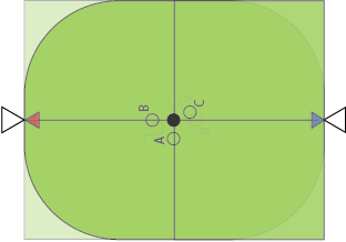 If this is the result you get, everything is exactly right and you can walk away happy.
Offset errors
Quite likely though, all will not be well. This may be because the wheels are not turning at the same speed, the robot is not balanced, there is some drag from, for example a bad castor, or any number of other problems. Suppose that, after a 180 degree turn, the robot is not lining up properly with the marks on the floor. What can you deduce about the error?
Lateral offset
Consider the case where the robot is turning about the location marked A in the diagram. After a 180 degree turn, it will be positioned like this:
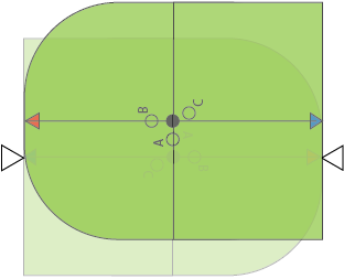
You can see that the front and rear of the robot are exactly in line with the marks but the robot is off to one side. A little thought should reveal that the robot offset is exactly twice the distance between the desired rotation centre and the actual rotation centre. Knowing the there is only a lateral offset can reduce the search for possible causes. Here it may be that the wheel speeds are not properly matched. or the wheels are not the same size.
Longitudinal offset
Perhaps the test is run and the robot ends up with the marks aligned like this:
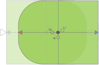
Now you can see that the robot has actually turned about the point marked B. Again, the amount by which the marks are displaced is exactly twice the distance between the desired centre of rotation and the actual centre of rotation. Now you can be pretty confident that the wheels are correctly sized and aligned and/or that the drive speeds are properly matched. This kind of error could be cause by excessive drag from a castor.
For a robot where the drive train is not exactly in the centre of the robot, this is what you will see anyway and is not necessarily an indication of an error. You can still do the test and get good information but you will have to make two sets of marks showing the expected start and end positions for your particular robot. Then you compare the actual end points with the expected endpoints exactly as before.
Combined errors
In practice, of course, the actual centre of rotation may be out of place in both axes. For example, if the robot turns about point C, the result will be like this:
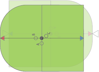
It is clear that there is a simple combination of each type of error and the individual offsets are calculated just like they were in the previous cases.
Correcting errors
For you, it may not matter if there is some small error. It may not even matter if the error is not consistent. For some tasks, it is just not too important. For me though, I want there to be no error if at all possible. In a micromouse, I really want there to be no lateral error and as little longitudinal error as I can manage. When setting up the sensors and turn parameters, the mouse position is actually the centre of rotation. This is the origin of the mouse local coordinate system. While it could be anywhere along the centre line of the mouse, you really do not want it to be off to one side. Think about what happens when you turn around in place while exploring. The mouse may have been properly positioned before the turn but it could now be too close to one wall after the turn.
So, I would want to correct any lateral errors first. Don’t try to correct both at the same time. They should be independent and can be corrected independently.
If you have a four-wheel micromouse like this one,
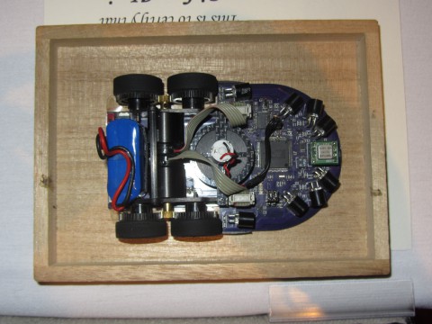
the centre of rotation may be closer to the front wheels than the rear ones. Note that it is important that all four wheels make contact with the floor with the same force and it may be necessary to adjust that by correcting a twist in the chassis.
As ever, all the above may be obvious. Certainly, it is clear enough when you have discovered it, or had it pointed out, but it may not have come to you naturally. In that case, I hope this helps.