LCD testing for Decimus

Having installed the LCD, it was time to get the code working for it. First I realised that it may not have been so clever to put the LCD on the same SPI port as the encoders. This will mean that I have to take care that the encoders are not being read when the LCD is active. Since the encoders are sampled every interrupt, it means turning them off while writing to the screen. That, in turn, means not writing to the screen while moving, or holding position. I may end up having to patch the board to put the LCD on the other SPI port. In fact, I wish I had done that in the first place as it would just share lines with the UART and I could easily switch between the UART and the SPI for writing debugging messages. Ah well, live and learn. (more…)
Continue ReadingLCD testing for Decimus

Wheel assemblies for Decimus 2

The wheels have given me so much trouble that it all has to be downhill from here. This is how they are put together.Good wheels are essential in a micromouse. We want something that is robust, reliable and capable of precision, repeatable movement. There should be no wobbling and shaking and their relationship to the body of the mouse must be constant, or at least predictable. Clearly, the grip of the tyre is essential for high performance. The wheel in a simple mouse will probably need to carry the final stage reduction gear. (more…)

Continue ReadingWheel assemblies for Decimus 2

Primus in control and moving

After a lot of messing about with other stuff, Primus is now back on track and has the basic motion code written and installed. Movement within the maze is possible with steering off the walls to prevent collisions; fixed size moves and in-place turns are functioning; forward error detection and correction is working.

(more…)

Continue ReadingPrimus in control and moving

Formula1 Rat Race – How fast is that?

The schools competition includes a head-to-head drag race called Formula 1. If you want to know how fast you have to be, read this.The Formula 1 Rat Race track is straight and 7.2m long. At the start end is an area 375mm long where the rat starts from. At the end is a 1.2m long area for the mouse to come to a rest. It must not overshoot this area of penalties will be incurred that will almost certainly eliminate the rat from the competition. (more…)

Continue ReadingFormula1 Rat Race – How fast is that?

Feeling our way with sensors

The sensors are a critical part of a micromouse. Primus uses six infra-red reflective sensors. Here is code to test that they are working.Now that we have a nice display to show what the sensor reading are, we can get that module tested. Since the hardware is very simple, there is not a lot to go wrong. Yet somehow I had a dead sensor when I first tested the Primus prototype. It was a simple dry joint that would have been detected by more careful inspection of the board. (more…)

Continue ReadingFeeling our way with sensors

Adding a timer and the graphical LCD

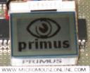
primus micromouse splash screenThis is a fairly big jump. With the LEDs and buttons tested, it is time to add the main graphical display, made from a Nokia cellphone display. Also, there is the main system timer event.

The simple user IO is working, and it is time to add a system timer. This will generate an interrupt every millisecond. In the final mouse a lot of work will be done in here – processing buttons, driving the LEDs, reading sensors and calculating drive signals for the motors.While that may seem a lot in a millisecond, the dsPIC used in primus can execute about 16,000 instructions in that tme and we should only need a small proportion of that time. (more…)

Continue ReadingAdding a timer and the graphical LCD

Revised schematics and pin functions

After a bit more thought, there is now a new set of pin assignments for the Primus micromouse, along with a corresponding schematic.The problem with Primus was that it is not possible to generate two independant pulse trains from the PWM generators. All the PWM channels have to share a common time base.The Output Compare peripherals on the dsPIC30F4011 can generate up to two independant pulse trains in hardware but one of the time bases must come from Timer 2 which is needed for counting steps sent to the motors. One of the fundamental design decisions on Primus is to drive the two steppers at high speeds without any interrupt service routine soaking up processor cycles.It seems that one motor will have to be driven from an OC channel and the other from a PWM channel. (more…)

Continue ReadingRevised schematics and pin functions