Having installed the LCD, it was time to get the code working for it. First I realised that it may not have been so clever to put the LCD on the same SPI port as the encoders. This will mean that I have to take care that the encoders are not being read when the LCD is active. Since the encoders are sampled every interrupt, it means turning them off while writing to the screen. That, in turn, means not writing to the screen while moving, or holding position. I may end up having to patch the board to put the LCD on the other SPI port. In fact, I wish I had done that in the first place as it would just share lines with the UART and I could easily switch between the UART and the SPI for writing debugging messages. Ah well, live and learn.Turns out I wired up the LCD module incorrectly and destroyed it. Fortunately I had several spares so I built up another. These things are cheaper than text displays so it is no great loss. Attaching wires to the LCD display is easier than you might think. As supplied, the Nokia 3410 LCD display comes as part of a replacement panel that looks like this:
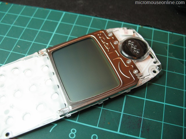
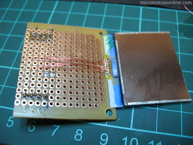
Prise off the aluminium surround and the actual display element will come free. It is attached with a small amount of adhesive or double-sided tape. Sprung contacts serve to make the connection between the display and the phone main board. These too are attached with adhesive and can be removed to reveal a row of small pads to which you can solder wires. [See warning in comment below before removing this connector]. I used polyurethane coated copper wire from a Verowire pen (about 0.15mm diameter). The ends of the wires are stripped by simply heating with the soldering iron set to about 400 degrees Fahrenheit:

These wires are then taken to pin headers on a matrix board so that the entire assembly can be plugged into the mouse when needed. once the connections have been tested, the LCD is held onto the carrier with some double-sided foam adhesive pads.
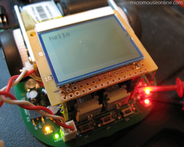
It does not weigh much and could probably be left in place when running. The mouse looks a lot better with it off though. For now, a simple ‘hello’ is enough to show that it works.
Beware – Not all Nokia LCD’s have the solder pads as described above. The ones I have bought have a connector block sandwiched between the plastic casing and the LCD, when you take the assembly apart you are left with nothing to solder too.
Until I did this one, I always soldered to the spring contacts. It was only after I accidently knocked them off that I found the pads underneath. I would not be at all surprised to find they don’t all have solder pads. It is probably safer to solder to the spring contacts.
Thanks for the warning.
I have been struggling with the Nokia 3410 display now for sometime. To-date I have not been able to get any response from 2 x LCD’s whatsoever. In your blog you say “I wired up the LCD module incorrectly and destroyed it”. What were the symptoms of destroying the LCD?
I am afraid I don’t remember. However, since I have several working test setups, I suppose I stuffed it into one of those and decided it was broken if it didn’t work. They are quite robust. I have connected them exactly in reverse without ill-effect. That happened because a couple of the on-line information sources have the pins shown the wrong way round. If you cannot get a response from the device at all try turning it around. Then consider that you may have been sold the wrong part.
Whatever Barry said, happened with me today!
I had already gone through this blog long time back, but on having the LCD in my hand, I was just too curious to see whether mine has the pads or not.
Curiosity killed the LCD!!!!