 With the sensors installed and the robot pretty well complete, it is time to see if they can actually do the job they were designed for. the idea is that the line of sensors will be able to measure the robots offset from the centre of the line over as wide a range as possible.
In a previous post, I described how the error could be determined very conveniently by looking at the difference in reading between two sensors. This is very true and perfectly valid for the case where there are three sensors. Or even two. However, I put five on Bob and wanted to get as much of a displacement as possible. After messing with the simple difference technique for a bit I decided to get on and do the job ‘properly’. Well, as properly as I could think of today at any rate.
Bob has five sensors arranged at fixed intervals of 0.5 inch. This spacing is determined mostly by the fact that the sensors are mounted on 0.1" pitch perfboard. The fixed spacing turns out to be important and very convenient. A typical set of sensor readings look like this:
| Sensor | 0 | 1 | 2 | 3 | 4 |
| Reading | 127 | 124 | 9 | 45 | 125 |
the sensors are numbered from left to right from the driver’s point of view. Each reading has been normalised to a maximum value of 127 representing the black background so the low values are sensors that can ‘see’ the white line. It should be apparent that the robot is off centre to the left by some small amount as sensor 3 can see the line but not as well as sensor 2. Usually only two sensors can see the line at once. The spacing is such that, as soon as sensor three stops seeing the line, sensor 1 starts to see it. A slightly closer spacing would be better for the technique I am describing. I think a sensor spacing equal to the line width would be best.
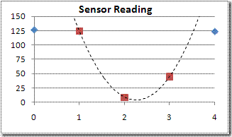
So, we are interested in the response of three sensors. The one with the lowest reading and the sensor either side of that. We can plot the readings on a graph and try to fit a curve to the three we are interested in. Something like this:

The curve is a quadratic and you can see that the turning point – the minimum value – is in between sensors 2 and 3. It is closer to sensor 2 as you might expect. Without drawing lots of examples, it should also be apparent that the turning point will move toward sensor 3 as the reading on that sensor gets smaller and that on sensor 2 gets bigger. In fact, that turning point allows us to interpolate the actual centre of the line quite accurately as long as the sensor spacing is regular and appropriate. On BOB they are a bit far apart but it still works out quite well.
How can we find the turning point? the curve is a quadratic and we have three points that lie on it. thus the equation can be solved using simultaneous equations. Remember those? A technique for solving these things is to calculate differences. Again, I won’t detail the entire process but just give the result.
We have three sensor readings s1, s2 and s3 corresponding to the position of three sensors at positions x1, x2, x3. If we take the distance between the sensors to be a single unit, the position of the turning point, relative to s2 is:

Only the division need cause any problems for the code and I am using C so I can let the compiler deal with that. To help with the division and to ensure there are no overflows or underflows, it is convenient to perform the first part and then pre-scale it by 256 before doing the division. The result will be a number between -128 and +128 representing the offset of the turning point from the middle of the three sensor readings.
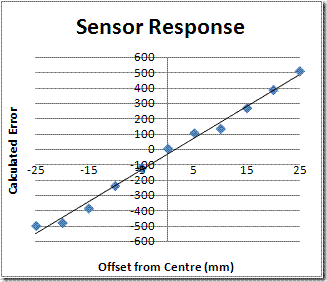
To test out the theory on Bob, I made up a rough test rig which would allow me to move a white line under the sensors in increments of 5mm and have the robot calculate its offset from centre. The test rig picture is at the top of this page. Here are a typical set of results:

Not perfect but they seem to do the job. The offset can be calculated over the full range of +/- 25mm from the centre. The results seem monotonic and fit a straight line quite well. Better spacing should improve this a bit but I shall leave them as they are for now. The way the ends of the range are dealt with could be improved since it should be possible to get good results out as far as +/- 40mm with this technique. Time is short however, so I will go with this for now
hello there,
i have the following doubt:
1.i think u mentioned somewhere that u r are using tcrt5000 as sensors.
2.i too use the same and convert the analog sensor output via a comparator into a digital output and feed the micro-controller(i am using atmel 8051).
3.if so, how r u setting the sensor values to discrete nos., say like 126,9,45………..etc?
I am afraid I use an ADC to get analogue values from the sensors. Otherwise, I guess you would have to have a potentiometer for each sensor to set the thresholds.