After the PCB order had been submitted I created the BOM and ordered the parts from Mouser for delivery a couple of days before the PCB. I tried hard to reduce the number of different parts. One big change from Zeetah V (ZV) to Zeetah VI (ZVI) was that I changed all parts from 0603 to 0402 except when the power or voltage required the larger part. This made fitting the parts for ZVI easier but also made routing 0.2mm traces with 0.2mm space a little harder. This meant that there were very few ZV parts I could use on ZVI.
 I would have used DigiKey but there were a couple of discrete parts that were out of stock/not available at DigiKey but Mouser had them. Also, it didn’t hurt that Mouser was about 10% less than Digikey. One aspect of the ordering process that was annoying was the price breaks. For several parts, I needed ten but it was cheaper to order 25! So, after entering the order, I went back and checked the price breaks and adjusted quantities to get the best price.
A couple of days after I submitted the board order to PCBCart, I received an email asking if a few holes could be non-plated. It turns out that I made a mistake and forgot to mark the drive motor/axle bracket and reset switch alignment holes as non-plated. So, after I responded that these should have been non-plated, they went ahead and modified the database to take this into account and released the board to production.
Around the same time, I saw the actual color of the soldermasks they offer and really liked the yellow one and thought it would be more visible than green or blue (the color I choose) but it was too late. Now I have to build ZVII so that I can try the yellow soldermask with black silkscreen!
The parts from Mouser arrived on 7/15 and the boards arrived from PCB Cart on 7/18 (as quoted by PCB Cart). The clarification/change for non-plated through holes had no impact on the delivery date!
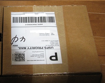
I was unable to receive the board package on the delivery day and I was pleasantly surprised and impressed to receive a note from the PCB cart sales team mentioning that FedEx had tried to deliver the package and could I make sure someone was around to receive it?
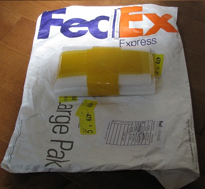
The boards were well packed and they had done a thorough job of documenting the shipment both for the US customs and for me. I had intended to order only five boards but their pricing structure is such that boards six through ten are $2.xx each and I figured why not. I suspect I will never use more than a couple of the boards but I have enough to experiment on other circuits if/when the need arises. I’ll add them to the collection of extra ZIII, ZIV and ZV boards I have.
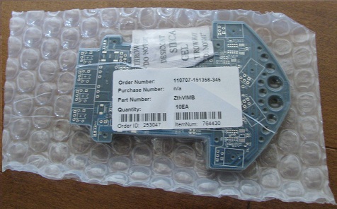
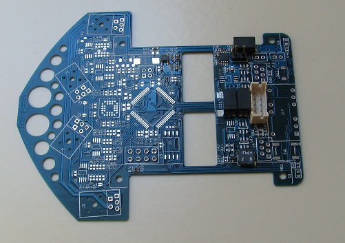
The boards were enclosed in vacuum sealed bubble wrap and included a desiccant package visible on the top of the picture.
Just before I ordered the boards, Peter and I had been discussing what needed to be specified in the order/ordering process to ensure that they would route the board the way I wanted. It turns what I had to do was put the outline on every layer. I also included a mechanical layer where I clearly showed the board outline, which areas needed to be routed out, the board thickness (0.031 inch), flatness requirement (5mil per inch.), board finish (HASL and soldermask over bare copper). I included this information in the special instruction section since their instructions/FAQ indicated that all this needed to be part of the order.
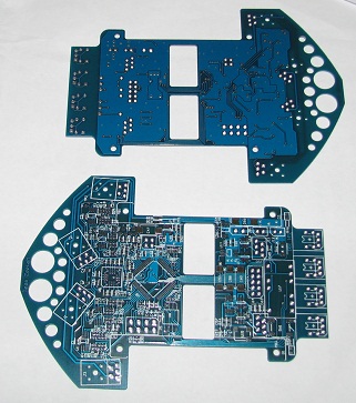 I was very relieved to see that the board outline and internal routing meet my requirements.
The PCBCart folks didn’t say anything about the sensor boards on the bottom. I tried to separate them using an Xacto Razor saw but cutting the board was harder than I thought it would be. So, I switched to using a jig saw and was able to cut the board pretty quickly. I then used a sanding block to clean up the edge.
 I finally had some time earlier today (7/23) and was able to go into work and start soldering parts. I made sure that no power and ground rails were shorted. During the soldering process I discovered that I was out of practice. I thought I would be able to attach on average a part a minute but setup, locating and attachment of the actual parts took much longer than that. I finally rediscovered the benefits of flux. Handling 0402 parts is a royal pain. I kept having too much or too little solder or I wasn’t happy how the part was laying on the board. The 0603 parts were so much easier…
I also found that I had left in a couple of pads with vias in them – I had been a little impatient at the end of the routing process and put a few via in pads to finish up the routing. One of the board houses had suggested I not do this, so apparently, I fixed all but two of them. PCB cart didn’t seem to care about this… I did find one pad didn’t have good solder coverage and also had a spot of silkscreen (found when looking at the pads under a microscope) on it. When I used an X-Acto knife to scrape the silkscreen off, I found that the soldermask was easier to remove than my experience on other boards. While this isn’t an issue, I don’t know if this is because it is blue soldermask and this doesn’t stick as well as the green soldermask or if something else is going on. Anyway, I’m not concerned.
I have the 5V and 3.3V voltage regulators on the board. I’ll power them up and make sure they work and then proceed to attach the CPU and remaining parts. I did find that I made a mistake on the keep-out footprint for the Aluminum Organic capacitors. I’m only able to install two where I expected to install three. Because of over design, I do not expect this to be material.
It looks like Pierre is also working on the mechanical design. I actually soldered up two boards – one with parts which Pierre needs to make sure clear the motor brackets and the one above which will turn into ZVI.
my brother thought that the drill may be biting into it/being machined too fast and suggests it might be an idea to use a smaller bit to:
a. give a better finish
b. reduce stresses caused in manufacture
i don’t know much about it but i thought id pass it on just in case 😀
Thank you. The chewed up section of the right shaft on the lower bracket occured during threading. The shaft was undersized by about 10 thou and there was not enough material left.
Hi Pierre.
What diameter are the axles? Will you remake to the same design?
Hello Peter,
I’m going to stay with 2mm and M1.6 screws. I resolved the threading issue but ordered some M1.2 screws and taps just in case. The wheels will be similar to the last ones, just a bit smaller and with a different number of teeth.
Regards,
Pierre
Hi, did you design and print the PCB board yourself?