Travelling to contests is great. Except for the bits and pieces that you need to lug around. For several years I have used a smart charger for my LiPo batteries. It is a fine charger but bulky. Along with its mains power supply it is about the size of a large laptop charger and needs several cables to join together. I decided to make a smaller, portable charging solution.
Having recently made a small STLINK/V2 board that was about as big as a thumb drive, I figured that I could get two single-cell LiPo chargers and a USB to Serial bridge into the same space. A single USB port would then run the serial bridge and provide the charge current and I could say goodbye to a bunch of wires and heavy boxes.
SERIAL
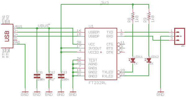
The serial bridge is a simple, standard design based on the common FT232RL. Aside from a few decoupling capacitors, the only other components needed would be a couple of LEDs to indicate activity on the RX and TX lines. These are not essential but it is comforting to see activity on the serial port. It reassures you that something is actually happening even though the terminal software might stubbornly refuse to show it.
For my application, I needed only a 3.3V connection and the FT232RL can be set up directly for that thanks to the on-board regulator. I also did not need any of the handshaking lines so only GND, RX and TX would be brought out of the board. The final circuit looked like this:
[UPDATE: Just noticed there should have been a ferrite bead on the VBUS line. Dang!]
CHARGER
For the charger, I could pick from a large range of available parts. I wanted to charge single cells to eliminate the risk of unbalanced cells in series-connected packs and I wanted easy current setting. Charge status LEDs would be goo to show me when the cells were charging, when they were charged and to indicate any errors. In Fort Worth, I discharged some cells below the threshold where my smart charger would do anything with them so I also wanted a device that would restore low-voltage cells to the point where they could be safely fast-charged. The first device I found that fitted these requirements and was both reasonably priced and easily available was the MCP73833 from Microchip.
Like the serial bridge, the circuit was really simple. Not as simple as I thought at first though since I left out the 10k resister on the thermal sensor pin and had to patch it in on the first batch of boards. Again, two LEDs indicate the charger status. I used a red LED to show charging and a green one to show complete. A single resistor sets the charge current.
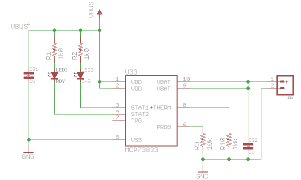
The cells I am using are 130mAh Hyperions. They can be safely charged at up to 5C I believe. Even so, I made up two chargers and chose 100mA for the charge current on one board and 180mA on another. A standard USB port can supply up to 500mA. I was a little concerned that the FT232RL might negotiate a low current connection but that seems not to be the case so it is possible to put both the FT232RL and two chargers on the same USB port.
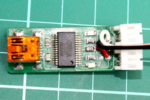
The boards came out pretty well I think and they work just fine. The serial bridge is all on one side and the chargers take up the other. Either side can be populated, or both. I prefer a flying lead for the serial connection but a 3-pin connector would also be suitable. On this sample board, I used the battery connectors to provide strain relief for the serial lead. You can see where I messed up these boards by leaving out the thermal sensor resistor so I had to patch it in afterward. Annoying but not too hard to fix. Since I have 20 or so of these boards, that is probably how they will all get done now rather than ordering another batch.

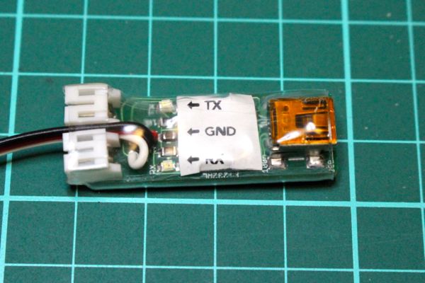
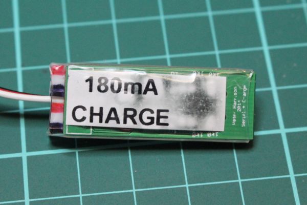
The labels sit under the clear heatshrink tube used to protect the circuits. The indicator LEDs are plenty bright enough to shine through the label. The discolouration is because I forgot that the labels are from a thermal printer and shrinking the tube nearly turned them completely black. I will use laser labels next time.
FT232RL on the FTDI site
MCP73833 on the Microchip site
How many battery sets do you have?
I just MCP73831 instead 73833 since it only has 5 pins. only use 1 led on to indicating charging and the led off when charging is done. pretty simply.
I normally keep three sets of batteries with each mouse. The MCP73831 is nice. I like to see a charged indication though so I am happy with the extra parts. Oh – the MCP73831 can do that too. Cool!
yeah, your IC has thermo shut off feature which is really cool. Guess MCP73831 is only for lazy people like me. LOL
Now I have 4 sets of batteries and 3 battery chargers(each one charges one set of battery), barely enough for continuous test for mouse.
So what current do you charge at?
100mah
my charge has slide switch switching between 100mah and 500mah.
my batteries are cheap so I can only charge at 1C
The design of my charger is at greenye.net
Hi, Peter and Green. We make a charging base (and programming) with magnetic socket. we use the MCP73213 inside the robot (it is the only charger with small dimension to charging 2S lipo). You can see our site pacabot.com
Our team really admire your work! thanks
great idea. You micromouse, zhonx3, looks really interesting.
Is there much micromouse activity where you are?