Finally, an official qualification run on a full size maze…
Saturday 11/27
Now that the mouse was working, I made another list of things I wanted to verify before the contest. I skipped breakfast and used the time to finish the front wall based longitudinal correction. I had coded the diagonal corrector the day before but hadn’t tested it.
Since it was qualification day, I was hoping that my turn to qualify would be later in the day and I would be able to use the time to test the new features and make sure I hadn’t broken anything. When I got there, I saw Dave and Peter picking up their numbered bibs (sorry Pete, I can’t remember their name) that you see all the contestants wearing. I set my stuff down and went over and picked mine up. This was unbelievably exciting for me because it is something I’ve wanted to do for years and I was finally doing it. I had a bit of good luck in that my qualification turn was in the middle of the pack – I was thirteenth. I figured that at seven minutes a person, I had about an hour and a half.
I went back to the table I was using on Friday and setup my stuff. I put the batteries I intended to use on trickle charge. By now the practice maze was very, very busy. So, I reset the target position from the center of the maze to coordinates (4,4) and I ran the mouse to see if the sensors were really working properly and sure enough, they were!
Then I decided to test the front wall based longitudinal correction and it would work sometimes but not at other times. Since this piece of code was new, I really focused on it and using the symptoms was able to figure out that I was using the raw sensor value to compute the correction rather than the location of the mouse! After I fixed this typo, I was able to verify that the correction was working. Phew.
As I was walking back to the computer, Dave came by to get me because they had called my name to come and be seated. If you look at the pictures, there is a set of chairs next to TV monitor where the contestants queue up. Since the number of entries is large, this is a great way to keep the contest running smoothly.
I started hurrying because the target cell was not correct. Dave reassured me that I had a few minutes – I then did a quick calculation and I had about fifteen to twenty minutes but I needed to be seated before my turn. I went back to the computer and changed the target to the center of the full size maze and I went back to the practice maze and made sure the mouse didn’t go to the target I was using. I then walked over to the qualification maze and took my seat.
At this point, I’m thinking to myself that I’ve written a lot of code in the last three days but haven’t really tested it all very thoroughly and on top of that, I just changed the target cell and didn’t make sure the mouse went to the right cell. While this did make me nervous, given where things were a few days ago, I think the code is working better today. I relax and enjoy the moment of being in the qualification group.
Finally, it is my turn to run ZV and my hands are shaking a bit but after a couple of deep breaths, I’m relaxed. I turn on the mouse and hit the start/stop button and off it goes. It takes the path I expect and is moving rather well. I see it over correct a few times and I also see that it is turning a bit later than it should which means it has to correct immediately. However, the front wall based longitudinal correction appears to be working well. The lateral correction is also working well. On the first run, it maps a good portion of the maze but miss maps a wall and drives into it. On the second run, the mouse makes it to the center and the feeling is just wonderful. On the third run, the mouse goes and explores something on the right hand side of the maze and again goes to the middle and then it finishes exploring the rest of the maze. This means the fourth run should be a “speed” run. Earlier in the morning, I had modified the path generator to generate paths using learning turns and not diagonals because I hadn’t tested the diagonal corrector. The mouse started out fine but then drove into a wall. The wall it drove into was in the same area as where it had crashed earlier, so I was pretty sure it had a mistake in the maze. So, after the fourth run, I mentioned to the judges that ZV was retiring because there was no point in running it again. However, due to the language barrier, I wasn’t able to get my point across and since I get five runs, went ahead and ran it again and it crashed in the same spot as run four. I was very excited and relieved that the mouse had made it to the center.
Later, after Dave finished he mentioned that he had asked Eric (his blog is here) to take pictures and videos of my runs. I’m very, very grateful for this. In my haste to leave home, I left the camera at home. I later ran the simulator with the qualification maze and it is clear that the mouse mis-mapped at least a couple of walls. How I wish I had data from the qualification run so that I could determine what happened. Now, I can only speculate…
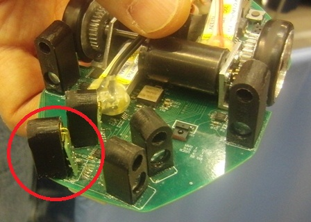
I wanted to use the contest to get test data and so, whenever I saw a free maze, I was doing practice runs. After a few runs, ZV is running better than the qualification run and another contestant put his mouse down in the maze and didn’t see ZV and the two collide! The right wall sensor block on ZV sheared off and in the process pulled off a couple of traces and the right diagonal sensor block came loose. So far the code doesn’t use the right wall sensor block but I think it may have been needed for diagonals. Once I start tuning diagonals, I’ll check if the sensor is needed or not. If it isn’t, I’ll remove the left wall sensor block also. If it is needed, I’ll add a couple of green wires to fix the traces that came off.
The rest of the time at the contest was just great because I could enjoy it as a spectator instead of having to deal with the pressure of being a contestant. The entries were just unbelievable. Peter has a great write up.
The official results are out and can be found at the New Technology Foundation Site
The New Technology Foundation, the folks that put on the contest, record the event and I believe even make a DVD. However, none of us from outside Japan have been able to figure out how to get a copy of the DVD. If you have any leads, please do share.
Pictures from Peter can be found at my Office Live Site
There is also a set of split zip files of video of ZV running in the qualification round.
Monday 11/29
I’m hoping to come back to the contest next year, so I wanted to become more familiar with the logistics. I found an ATM machine and withdrew some money. When I got back to the US, I checked and the conversion rate was about the same as at the airport.
On Monday, Peter, Dave and I met up with Lem Fugitt from http://www.robots-dreams.com/micromouse/ in Akihabara. Lem is incredibly knowledgeable and he gave us a guided tour of the area – we would have seen less than ¼ the things we did without him. It is just amazing how much robotics activity there is in Japan. As we were wandering around, we ran into Khiew Tzong and a few other folks.
I don’t think I would make the all-in-one units again. Making your own gears is fiddly and time consuming. Even if I cut my own gears again, I will still use two part drive units. one of the worst limitations is that you have to make the gear bigger than the wheel rim diameter in order to cut the teeth. This seriously constrains the range of sizes you can use.
Companies like Stock Drive Products can sell you modified gears with any size bore for a small extra cost. These can then be push fitted over lightweight commercial mini-z or dNano wheels. Much easier in the end.
Even with stock gears, if you have the ability to do the kind of machining needed to make an all-in-one unit, it would be no trouble to bore eisting gears into a ring that will push over a hub.
Gear cutting is certainly time consuming. Size limitations depend on the method used to cut the gears. If you use a shaper cutter, you can make any size gear with any number of teeth.
I have only what I can make with rather limited machining skills.
The method I used to make the gears is here:
http://www.helicron.net/workshop/gearcutting/
Nice website. The third method list is what I used. Commercial shaper cutters are very expensive. I tried using a steel spur gear as the cutter but was not happy the result. I ended up making my own on a little maxnc.
The down side of this method is that it is slow and you have to be able to accurately index the blank.
Cutting micromouse gears straight onto the hub with a CNC lathe:
I presume there is a thin parting tool creating a clearance area for the shaper tool to cut the teeth.
How do you create the shaping tool profile?
And, do you remount the wheel to bore out the ouetr face?
Oh, and why ABS?
You are correct. The thin parting tool can’t be seen in the video but it is in the 2nd tool holder — between the parting tool and the turning tool. The cut is made about 2:07 minutes into the video.
In this particular clip, I was a little aggressive on the turning feed. You can see the stock deform under the load. I slowed it down a bit on the final version.
I found a CAD drawing of the 30 tooth gear on a parts suppliers website and used that to made the NC file to cut the shaper. The shaper was cut with a dremel-type cut-off disk in a little MAXNC.
I do remount the wheel to cut the back side — but all critical cuts are done from the front to ensure concentricity.
I think I had some ABS laying around and used it for the wheels. I can’t say I put much thought into material selection.
For al the obviousness of using CNC for everything else to do with making the wheels and gears, for some reason it had not occurred to me to use CNC to make the cutter.
Which microcontroller did you use? Before you jump into making your own custom MCU board, how did you do the initial prototyping? Did you use any evaluation board? I guess you are using STM32. Is there any reason why STM32 is a better solution over NXP’s LPC for Micromouse?
I’m using the STM32F103 processor that has 512KB of flash and 64K of RAM. I didn’t use any board for prototyping. Peter has a reference for an STM32 board that is under $30 that seems like a nice prototyping board.
I think the reason the STM32 is better than the NXP devices is because the NXP doesn’t have enough encoder counters (at least it didn’t the last time I looked). The STM32 has all the right peripherals to make it the perfect micromouse chip.
There are many, many people using this processor for their mice.